浏览分类
Phoenix Contact QUINT4-PS/1AC/24DC/40 电源
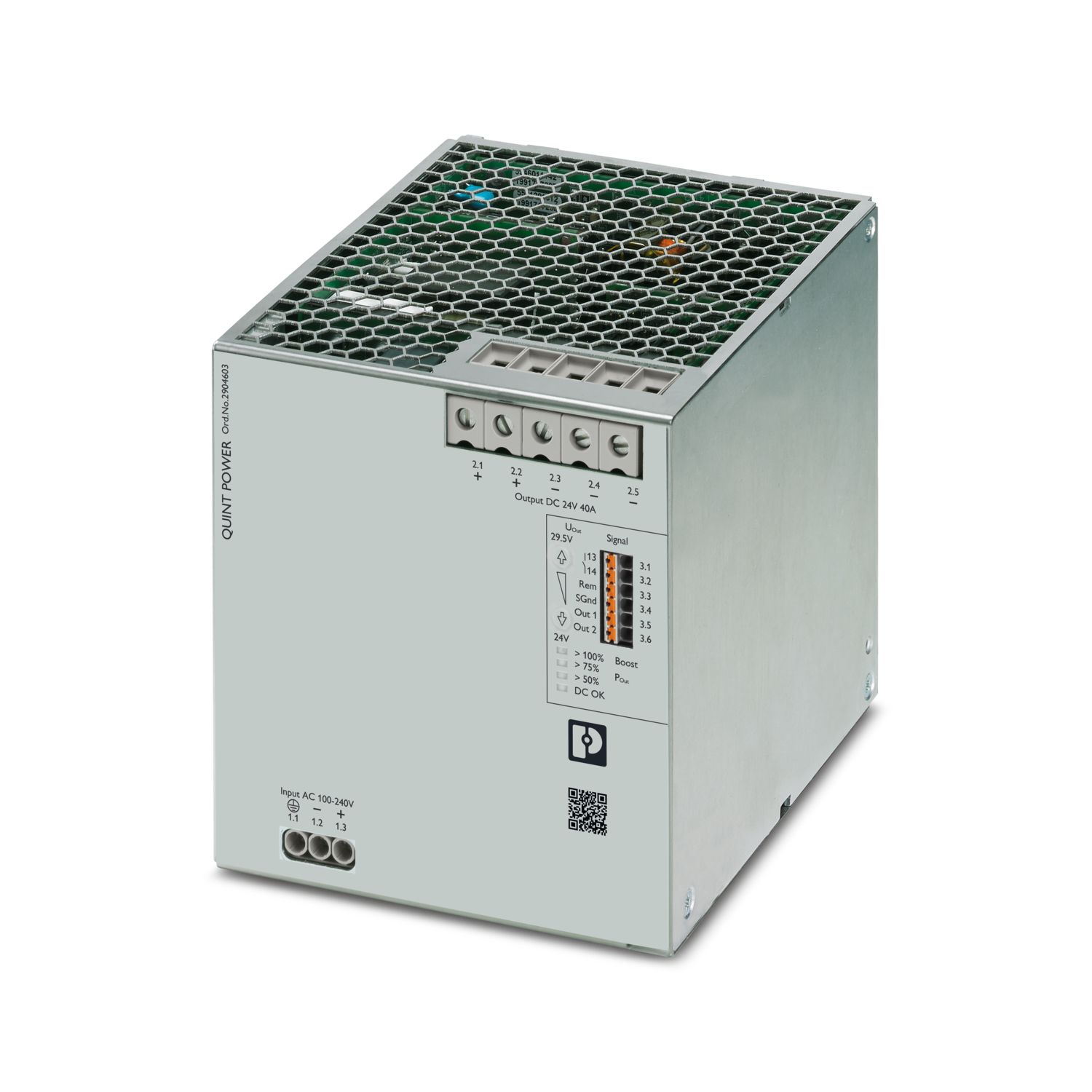
说明
Phoenix Contact QUINT4-PS/1AC/24DC/40 提供 24 V DC、40 A 输出,适合安装在 35 mm DIN 导轨上。
规格参数
| Brand | Phoenix Contact |
|---|---|
| Model | QUINT4-PS/1AC/24DC/40 |
| Order Number | 2904603 |
| HS Code | 850440 |
| Voltage | 10 V (Test Level 3) |
| Frequency | 16.7 Hz |
| Current | 20 A |
| Inrush current | typ. 12 A (at 25 °C) |
| Nominal output voltage | 24 V DC |
| Power dissipation SLEEP MODE | < 3 W (120 V AC) |
| Power dissipation SLEEP MODE | < 3 W (230 V AC) |
| Power loss nominal load max. | < 50 W (120 V AC) |
| Power loss nominal load max. | < 50 W (230 V AC) |
| Standard – Safety extra-low voltage | IEC 61010-1 (SELV) |
| Typical national grid voltage | 120 V AC |
| Voltage type of supply voltage | AC |
| Switching frequency | 85.00 kHz ... 107.00 kHz (Auxiliary converter stage) |
| Frequency range | 0 kHz ... 2 kHz |
| Input voltage range | 100 V AC ... 240 V AC -15 % ... +10 % |
| Nominal input voltage range | 100 V AC ... 240 V AC |
| Degree of protection | IP20 |
| Recommended breaker for input protection | 16 A ... 20 A (Characteristic B, C, D, K or comparable) |
| Vibration (operation) | 5 Hz ... 100 Hz resonance search 0.7g, 90 min., resonance frequency 0.7g, 90 min. (in accordance with DNV GL Class A) |
| EMC requirements for noise emission | EN 61000-6-3 |
| EMC requirements for noise emission | EN 61000-6-4 |
| EMC requirements for noise immunity | EN 61000-6-1 |
| EMC requirements for noise immunity | EN 61000-6-2 |
| EMC requirements for power supply | IEC 61850-3 (G,H) |
| EMC requirements for power supply | EN 61000-6-5 (switching devices) |
| REACH candidate substance (CAS No.) | Lead (CAS: 7439-92-1) |
| Shipbuilding approval | DNV GL |
| Additional text | 120 V AC |
| Additional text | 230 V AC |
| Additional text | Area power distribution |
| Additional text | Bridge and deck area |
| Additional text | 60 s |
| Additional text | 3 s |
| Additional text | DC, 60 s |
| Additional text | Test Level 2 |
| Ambient temperature (operation) | -25 °C ... 70 °C (> 60 °C Derating: 2,5 %/K) |
| Ambient temperature (start-up type tested) | -40 °C |
| Ambient temperature (storage/transport) | -40 °C ... 85 °C |
| Analog | 4 mA ... 20 mA ±5 % (Load ≤400 Ω) |
| Approval - requirement of the semiconductor industry with regard to mains voltage dips | SEMI F47-0706, EN 61000-4-11 |
| Battery charging | DIN 41773-1 |
| Climatic class | 3K3 (in acc. with EN 60721) |
| CO2e kg | 63.176 kg CO2e |
| Comments | Criterion A |
| Comments | Criterion A: 0.5 / 1 / 25 / 30 periods |
| Comments | Criterion A: 0.5 / 1 period Criterion B: 5 / 50 / 250 periods |
| Conductor cross-section AWG max. | 10 |
| Conductor cross-section AWG max. | 6 |
| Conductor cross-section AWG max. | 16 |
| Conductor cross-section AWG min. | 24 |
| Conductor cross-section AWG min. | 20 |
| Conductor cross-section flexible max. | 4 mm² |
| Conductor cross-section flexible max. | 16 mm² |
| Conductor cross-section flexible max. | 1.5 mm² |
| Conductor cross-section flexible min. | 0.2 mm² |
| Conductor cross-section flexible min. | 0.5 mm² |
| Conductor cross-section, rigid max. | 6 mm² |
| Conductor cross-section, rigid max. | 16 mm² |
| Conductor cross-section, rigid max. | 1 mm² |
| Conductor cross-section, rigid min. | 0.2 mm² |
| Conductor cross-section, rigid min. | 0.5 mm² |
| Connection in parallel | yes, for redundancy and increased capacity |
| Connection in series | yes |
| Connection method | Screw connection |
| Connection method | Push-in connection |
| Contact discharge | 8 kV (Test Level 4) |
| Control deviation | < 0.5 % (Static load change 10 % ... 90 %) |
| Control deviation | < 1 % (Dynamic load change 10 % ... 90 %, (10 Hz)) |
| Control deviation | < 0.25 % (change in input voltage ±10 %) |
| Control input (configurable) Rem | Output power ON/OFF (SLEEP MODE) |
| Crest factor | typ. 1.5 (120 V AC) |
| Crest factor | typ. 1.6 (230 V AC) |
| Criterion A | Normal operating behavior within the specified limits. |
| Criterion B | Temporary impairment to operational behavior that is corrected by the device itself. |
| Criterion C | Temporary adverse effects on the operating behavior, which the device corrects automatically or which can be restored by actuating the operating elements. |
| Csa | CAN/CSA-C22.2 No. 60950-1-07 |
| CSA | CSA-C22.2 No. 107.1-01 |
| Current | 40 A |
| Current consumption | 13.6 A (100 V AC) |
| Current consumption | 10 A (120 V AC) |
| Current consumption | 5.2 A (230 V AC) |
| Current consumption | 5.4 A (240 V AC) |
| Current consumption | 12 A (110 V DC) |
| Current consumption | 5 A (250 V DC) |
| Default | Output power ON (>40 kΩ/24 V DC/open bridge between Rem and SGnd) |
| Default | 24 V DC 20 mA 24 V DC for U Out > 0.9 x U Set |
| Default | 24 V DC 20 mA 24 V DC for P Out < P N |
| Default | closed (U out > 0.9 U Set ) |
| Degree of pollution | 2 |
| Depth | 140 mm |
| Derating | > 60 °C ... 70 °C (2.5 %/K) |
| Digital | 24 V DC 20 mA |
| Digital | 24 V DC 1 A |
| Digital | 30 V AC/DC 0.5 A |
| Discharge current to PE | < 3.5 mA |
| Discharge current to PE | 1.7 mA (264 V AC, 60 Hz) |
| Discharge in air | 15 kV (Test Level 4) |
| Dnv | Class A |
| DNV | Class B |
| Dynamic Boost (I Dyn.Boost ) | 60 A (5 s) |
| ECLASS-13.0 | 27040701 |
| ECLASS-15.0 | 27040701 |
| Efficiency | typ. 94.8 % (120 V AC) |
| Efficiency | typ. 95.9 % (230 V AC) |
| Electric strength, max. | 300 V AC 60 s |
| Electromagnetic compatibility | Conformance with EMC Directive 2014/30/EU |
| Environment friendly use period (EFUP) | EFUP-25 An article-related China RoHS declaration table can be found in the download area for the respective article under "Manufacturer declaration". For all articles with EFUP-E, no China RoHS declaration table issued and required. |
| Environmental protection directive | RoHS Directive 2011/65/EU |
| Environmental protection directive | WEEE |
| Environmental protection directive | Reach |
| ETIM 10.0 | EC002540 |
| Exemption | 7(a), 7(c)-I |
| Feedback voltage resistance | ≤ 35 V DC |
| Frequency | 50 Hz |
| Frequency | 60 Hz |
| Frequency | 0 Hz |
| Frequency range | 80 MHz ... 1 GHz |
| Frequency range | 1 GHz ... 6 GHz |
| Frequency range | 0.15 MHz ... 80 MHz |
| Frequency range | 50 Hz ... 60 Hz |
| Frequency range (f N ) | 50 Hz ... 60 Hz -10 % ... +10 % |
| Frequency range (f N ) | 16.7 Hz (acc. to EN 50163) |
| Fulfills EU RoHS substance requirements | Yes |
| Fuse protection (secondary side) | electronic |
| Fuse protection (secondary side) | thermal-magnetic |
| Fuse protection (secondary side) | thermal |
| HART FSK Physical Layer Test Specification Compliance | Output voltage U Out compliant |
| Height | 130 mm |
| Hood version | Stainless steel X6Cr17 |
| Housing material | Metal |
| Input | 4 kV (Test Level 4 - asymmetrical) |
| Input | typ. 3 kV (Test Level 4 - symmetrical) |
| Input | typ. 6 kV (Test Level 4 - asymmetrical) |
| Input | 2 kV (Test Level 4 - symmetrical) |
| Input fuse | 16 A (slow-blow, internal) |
| Input voltage range | 110 V DC ... 250 V DC -18 % ... +40 % |
| Input, output (test level 1) | 100 kHz 1 MHz (Test Level 3 - symmetrical) |
| Input, output (test level 2) | 10 MHz |
| Input, output (test level 3) | 100 kHz 1 MHz (Test Level 3 - asymmetrical) |
| Input/output/signal | asymmetrical |
| Inrush current integral (I 2 t) | < 1 A 2 s |
| Inrush current limitation | 12 A (after 1 ms) |
| Installation distance right/left | 5 mm / 5 mm |
| Installation distance top/bottom | 50 mm / 50 mm |
| Insulation voltage input/output | 4 kV AC (type test) |
| Insulation voltage input/output | 2 kV AC (routine test) |
| Low Voltage Directive | Conformance with Low Voltage Directive 2014/35/EC |
| Magnetic circuit breaker tripping | A1...A40 / B2...B25 / C1...C13 / Z1...Z16 |
| Mains buffering time | typ. 29 ms (120 V AC) |
| Mains buffering time | typ. 32 ms (230 V AC) |
| Max. permissible relative humidity (operation) | ≤ 95 % (at 25 °C, non-condensing) |
| Maximum altitude | ≤ 5000 m (> 2000 m, observe derating) |
| Maximum no-load power dissipation | < 4 W (120 V AC) |
| Maximum no-load power dissipation | < 4 W (230 V AC) |
| Minimum order quantity | 1 pc |
| Mounting position | horizontal DIN rail NS 35, EN 60715 |
| Mounting type | DIN rail: 35 mm |
| MTBF (IEC 61709, SN 29500) | > 934000 h (25 °C) |
| MTBF (IEC 61709, SN 29500) | > 555000 h (40 °C) |
| MTBF (IEC 61709, SN 29500) | > 249000 h (60 °C) |
| Network type | Star network |
| No-load proof | yes |
| Nominal input voltage range | 110 V DC ... 250 V DC |
| Nominal output current (I N ) | 40 A |
| Nominal power consumption | 1064 VA |
| Number of periods | 0.5 / 1 / 25 / 30 periods |
| Number of periods | 5 / 10 / 50 periods |
| Number of periods | 0,5 / 1 / 5 / 50 / 250 periods |
| Number of phases | 1 |
| Output | 4 kV (Test Level 4 - asymmetrical) |
| Output | 1 kV (Test Level 3 - symmetrical) |
| Output | 2 kV (Test Level 3 - asymmetrical) |
| Output power | 960 W |
| Output power | 1080 W |
| Output power | 1440 W |
| Overvoltage category (EN 61010-1) | II (≤ 5000 m) |
| Overvoltage category (EN 62477-1) | III (≤ 2000 m) |
| P Out | > 100 % (LED lights up yellow, output power > 960 W) |
| P Out | > 75 % (LED lights up green, output power > 720 W) |
| P Out | > 50 % (LED lights up green, output power > 480 W) |
| Packing unit | 1 pc |
| PE | 2.5 kV AC (type test) |
| PE | 0.5 kV DC (type test) |
| PE | 2.4 kV AC (routine test) |
| PE | 0.5 kV DC (routine test) |
| Product key | CMPI13 |
| Product type | Power supply |
| Protection against overvoltage at the output (OVP) | ≤ 32 V DC |
| Protection class | I |
| Rail applications | EN 50121-3-2 |
| Rail applications | EN 50121-4 |
| Rail applications | EN 50121-5 |
| Rail applications | EN 50163 |
| Rail applications | IEC 62236-3-2 |
| Rail applications | IEC 62236-4 |
| Rail applications | IEC 62236-5 |
| Residual ripple | < 50 mV PP (with nominal values) |
| Scip | 4654ca05-2cdc-49da-8da0-92691aa78cca |
| Selective Fuse Breaking (I SFB ) | 215 A (15 ms) |
| Setting range of the output voltage (U Set ) | 24 V DC ... 29.5 V DC (constant capacity) |
| Shock | 11 ms, 15 g, in each space direction (according to IEC 60068-2-27) |
| Short-circuit-proof | yes |
| Side element version | Aluminum |
| Signal | 4 kV (Test Level 4 - asymmetrical) |
| Signal ground SGnd | Reference potential for Out1, Out2, and Rem |
| Signal option | Output current |
| Signal option | Output voltage |
| Signal option | Output power |
| Signal option | U IN input voltage OK |
| Signal option | Operating hours |
| Signal option | Early warning of high temperatures |
| Signal option | OVP voltage limitation active |
| Signals (test level 1) | 100 kHz 1 MHz (Test Level 3 - symmetrical) |
| Signals (test level 2) | 100 kHz 1 MHz (Test Level 3 - asymmetrical) |
| Single conductor/flexible terminal point with ferrule with plastic sleeve, max. | 4 mm² |
| Single conductor/flexible terminal point with ferrule with plastic sleeve, max. | 16 mm² |
| Single conductor/flexible terminal point with ferrule with plastic sleeve, max. | 0.75 mm² |
| Single conductor/flexible terminal point with ferrule with plastic sleeve, min. | 0.25 mm² |
| Single conductor/flexible terminal point with ferrule with plastic sleeve, min. | 0.5 mm² |
| Single conductor/flexible terminal point with ferrule with plastic sleeve, min. | 0.2 mm² |
| Single conductor/flexible terminal point with ferrule without plastic sleeve, max. | 4 mm² |
| Single conductor/flexible terminal point with ferrule without plastic sleeve, max. | 16 mm² |
| Single conductor/flexible terminal point with ferrule without plastic sleeve, max. | 1.5 mm² |
| Single conductor/flexible terminal point with ferrule without plastic sleeve, min. | 0.25 mm² |
| Single conductor/flexible terminal point with ferrule without plastic sleeve, min. | 0.5 mm² |
| Single conductor/flexible terminal point with ferrule without plastic sleeve, min. | 0.2 mm² |
| Siq | BG (type approved) |
| Standard - Electrical safety | IEC 61010-2-201 (SELV) |
| Standard - Safe isolation | IEC 61558-2-16 |
| Standard - Safe isolation | IEC 61010-2-201 |
| Standard - safety for equipment for measurement, control, and laboratory use | IEC 61010-1 |
| Standard - Safety of transformers | EN 61558-2-16 |
| Standard – Limitation of mains harmonic currents | EN 61000-3-2 |
| Standard – Safety extra-low voltage | IEC 61010-2-201 (PELV) |
| Standards/regulations | EN 55016 |
| Standards/regulations | EN 61000-6-3 (Class B) |
| Standards/regulations | Additional basic standard EN 61000-6-5 (immunity in switching devices), IEC/EN 61850-3 (power supply) |
| Standards/regulations | EN 61000-3-2 |
| Standards/regulations | EN 61000-3-2 (Class A) |
| Standards/regulations | EN 61000-3-3 |
| Standards/regulations | EN 61000-4-2 |
| Standards/regulations | EN 61000-4-3 |
| Standards/regulations | EN 61000-4-4 |
| Standards/regulations | EN 61000-4-5 |
| Standards/regulations | EN 61000-4-6 |
| Standards/regulations | EN 61000-4-8 |
| Standards/regulations | EN 61000-4-11 |
| Standards/regulations | EN 61000-4-9 |
| Standards/regulations | EN 61000-4-12 |
| Standards/regulations | EN 61000-4-16 |
| Standards/regulations | EN 61000-4-18 |
| Standards/regulations | EN 61000-4-10 |
| Static Boost (I Stat.Boost ) | 45 A |
| Stripping length | 8 mm |
| Stripping length | 10 mm |
| Switching frequency | 45.00 kHz ... 200.00 kHz (Main converter stage) |
| Switching frequency | 50.00 kHz ... 500.00 kHz (PFC stage) |
| Temperature | 40 °C |
| Temperature | 25 °C |
| Temperature code | T4 (-25 ... +70 °C; > 60 °C, Derating: 2,5 %/K) |
| terminal blocks) | V0 |
| Test field strength | 20 V/m (Test Level 3) |
| Test field strength | 10 V/m (Test Level 3) |
| Test field strength | 100 A/m |
| Test field strength | 1 kA/m |
| Test field strength | 300 A/m |
| Test field strength | 1000 A/m |
| Test field strength | 110 A/m |
| Test level 1 | 15 Hz 150 Hz (Test Level 4) |
| Test level 1 | 100 kHz |
| Test level 2 | 150 Hz 1.5 kHz (Test Level 4) |
| Test level 2 | 1 MHz |
| Test level 3 | 1.5 kHz 15 kHz (Test Level 4) |
| Test level 4 | 15 kHz 150 kHz (Test Level 4) |
| Test level 5 | 16.7 Hz 50 Hz 60 Hz (Test Level 4) |
| Test level 6 | 150 Hz 180 Hz (Test Level 4) |
| Test level 7 | 16.7 Hz 50 Hz 60 Hz (Test Level 4) |
| Tightening torque max | 0.6 Nm |
| Tightening torque max | 1.5 Nm |
| Tightening torque, min | 0.5 Nm |
| Tightening torque, min | 1.2 Nm |
| Time | 394000 h |
| Time | 452000 h |
| Time | 320000 h |
| Time | 422000 h |
| Time | 113000 h |
| Time | 149000 h |
| Types of signaling | LED |
| Types of signaling | Floating signal contact |
| Types of signaling | Active signal output Out1 (digital, configurable) |
| Types of signaling | Active signal output Out2 (analog, configurable) |
| Types of signaling | Remote contact |
| Types of signaling | Signal ground SGnd |
| Typical national grid voltage | 230 V AC |
| U Out | > 0.9 x U Set (LED lights up green) |
| U Out | < 0.9 x U Set (LED flashes green) |
| UL approvals | UL Listed UL 508 |
| UL approvals | UL 121201 & CSA C22.2 No. 213-17 Class I, Division 2, Groups A, B, C, D T4 (Hazardous Location) |
| UNSPSC 21.0 | 39121000 |
| Voltage | 230 V AC |
| Voltage | 30 V 3 V |
| Voltage | 3 V |
| Voltage | 3 V 30 V |
| Voltage | 30 V |
| Voltage | 30 V (Permanent) |
| Voltage | 300 V (1 s) |
| Voltage | 1 kV |
| Voltage | 2.5 kV |
| Voltage dip | 70 % |
| Voltage dip | 40 % |
| Voltage dip | 0 % |
| Voltage type of supply voltage | DC |
| Weight per piece (excluding packing) | 2,887 g |
| Weight per piece (including packing) | 3,250 g |
| Width | 120 mm |
| With protective coating | no |