Parcourir les categories
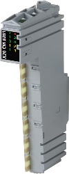
Module E/S mixte B&R X20CM8281
Description
Le module E/S mixte B&R X20CM8281 réunit 4 entrées numériques et 2 sorties numériques.
Specifications
| Brand | B&R |
|---|---|
| MPN | X20CM8281 |
| Current | 0x7FFF |
| Counter frequency | Max. 20 kHz |
| Current | 0x0000 |
| Current | INT 0x0000 - 0x7FFF / 1 LSB = 0x0008 = 4.883 µA |
| Current | 0 to 20 mA = 0.009 %/°C 4 to 20 mA = 0.0113 %/°C |
| Current | INT 0x0000 - 0x7FFF / 1 LSB = 0x0010 = 9.766 µA |
| Current | 0.014 %/°C |
| Current | 0 to 20 mA = 0.004 %/°C 4 to 20 mA = 0.005 %/°C |
| Current | Max. load is 400 Ω |
| Current | 0.03 %/°C |
| Current | Max. ±50 mA |
| Current | 12-bit |
| Current | Max. 0.5%, from 1 Ω → 400 Ω, resistive |
| Input voltage | 24 VDC -15% / +20% |
| Nominal output current | 0.5 A |
| Nominal voltage | 24 VDC |
| Nominal voltage | 24 VDC |
| Switching voltage | 24 VDC -15% / +20% |
| Total nominal current | 1 A |
| Voltage | 0x7FFF |
| Voltage | 0x8001 |
| Voltage | INT 0x8001 - 0x7FFF / 1 LSB = 0x0008 = 2.441 mV |
| Voltage | 0.01%/°C |
| Voltage | INT 0x8001 - 0x7FFF / 1 LSB = 0x0010 = 4.882 mV |
| Voltage | 0.012%/°C |
| Voltage | 0.002%/°C |
| Voltage | Max. ±10 mA, load ≥ 1 kΩ |
| Voltage | 0.0075% / °C |
| Voltage | Max. ±15 V |
| Voltage | ±12-bit |
| Voltage | Max. 0.02%, from 10 MΩ → 1 kΩ, resistive |
| Voltage | >1 MΩ |
| Input frequency | Max. 20 kHz |
| Settling time on output change over entire range | 1 ms |
| Input protection | Protection against wiring with supply voltage |
| Output protection | Thermal shutdown in the event of overcurrent or short circuit, integrated protection for switching inductive loads, reverse polarity protection |
| Output protection | Short-circuit proof |
| ABS | Yes |
| Additional functions | 20 kHz event counting, gate measurement |
| Analog inputs | Yes, using LED status indicator and software |
| ATEX | Zone 2, II 3G Ex nA nC IIA T5 Gc IP20, Ta (see X20 user's manual) FTZÚ 09 ATEX 0083X |
| B&R ID code | 0x24C3 |
| Braking voltage when switching off inductive loads | Typ. 50 VDC |
| Bus | 0.01 W |
| BV | EC33B Temperature: 5 - 55°C Vibration: 4 g EMC: Bridge and open deck |
| CCS | Yes |
| CE | Yes |
| Connection type | 1-wire connections |
| Connection type | 1-wire connections |
| Conversion procedure | Successive approximation |
| Conversion time | 400 µs, conversion runs asynchronous to the X2X Link cycle |
| Conversion time | 300 µs, conversion runs asynchronous to the X2X Link cycle |
| Counter size | 16-bit |
| Counter size | 16-bit |
| CRA (Cyber Resilience Act) | In preparation |
| Diagnostic status | Output monitoring with 10 ms delay |
| Digital converter resolution | 12-bit |
| Digital outputs | Yes, using LED status indicator and software (output error status) |
| Electrical isolation | Channel isolated from bus Channel not isolated from channel |
| Evaluation | Each negative edge, cyclic counter |
| Evaluation | Positive edge - Negative edge |
| Event counters | Input 1 |
| Event counters | Input 3 |
| Execution | Current-sourcing FET |
| Gain | 0 to 20 mA = 0.08% / 4 to 20 mA = 0.1% |
| Gain | 0.08% |
| Gain | 0.05% |
| Gain | 0.04% |
| Hardware | ≤2 µs |
| HazLoc | cCSAus 244665 Process control equipment for hazardous locations Class I, Division 2, Groups ABCD, T5 |
| High | >15 VDC |
| Horizontal | Yes |
| Horizontal mounting orientation | -25 to 60°C |
| Input | ±10 V or 0 to 20 mA / 4 to 20 mA, via different terminal connections |
| Input circuit | Sink |
| Input filter | Second-order low-pass filter / Cutoff frequency 1 kHz |
| Input resistance | Typ. 7.18 kΩ |
| Input type | Single-ended |
| Installation elevation above sea level | Reduction of ambient temperature by 0.5°C per 100 m |
| Installation elevation above sea level | No limitation |
| Installation elevation above sea level | IP20 |
| Insulation voltage between channel and bus | 500 V eff |
| Insulation voltage between channel and bus | 500 V eff |
| Insulation voltage between channel and bus | 500 V eff |
| Insulation voltage between channel and bus | 500 V eff |
| Internal | 48 MHz, 24 MHz, 12 MHz, 6 MHz, 3 MHz, 1.5 MHz, 750 kHz, 375 kHz, 187.5 kHz |
| Internal I/O | 1.75 W |
| KC | Yes |
| KR | Yes |
| Leakage current when the output is switched off | 5 µA |
| Length of pause between pulses | ≥100 µs |
| LR | ENV1 |
| Module run/error | Yes, using LED status indicator and software |
| Offset | 0 to 20 mA = 0.03% / 4 to 20 mA = 0.16% |
| Offset | 0.02% |
| Offset | 0.125% |
| Offset | 0.0225% |
| Operation | 5 to 95%, non-condensing |
| Output | ±10 V or 0 to 20 mA, via different terminal connections |
| Output circuit | Source |
| Output format | INT |
| Pitch | 12.5 +0.2 mm |
| Pulse length | ≥20 µs |
| Quantity | 2 |
| Quantity | 1 |
| Quantity | 4 |
| Quantity | 2 |
| Quantity | 1 |
| Quantity | 1 |
| R DS(on) | 105 mΩ |
| Resistive load | Max. 100 Hz |
| Signal form | Square wave pulse |
| Signal form | Square wave pulse |
| Software | Default 1 ms, configurable between 0 and 25 ms in 0.2 ms increments |
| Status indicators | I/O function per channel, operating state, module status |
| Storage | -40 to 85°C |
| Storage | 5 to 95%, non-condensing |
| Supported inputs | Input 4 |
| Switch on/off behavior | Internal enable relay for startup and errors |
| Switch-on in the event of overload shutdown or short-circuit shutdown | Approx. 10 ms (depends on the module temperature) |
| Switching threshold | Typ. 3.3 mA |
| Switching threshold | Type 1 |
| Transport | -40 to 85°C |
| Transport | 5 to 95%, non-condensing |
| UKCA | Yes |
| UL | cULus E115267 Industrial control equipment |
| Vertical | Yes |
| Vertical mounting orientation | -25 to 50°C |