Kategorien durchsuchen
Phoenix Contact TRIO3-PS/1AC/24DC/10/4C/IOL Netzteil
Beschreibung
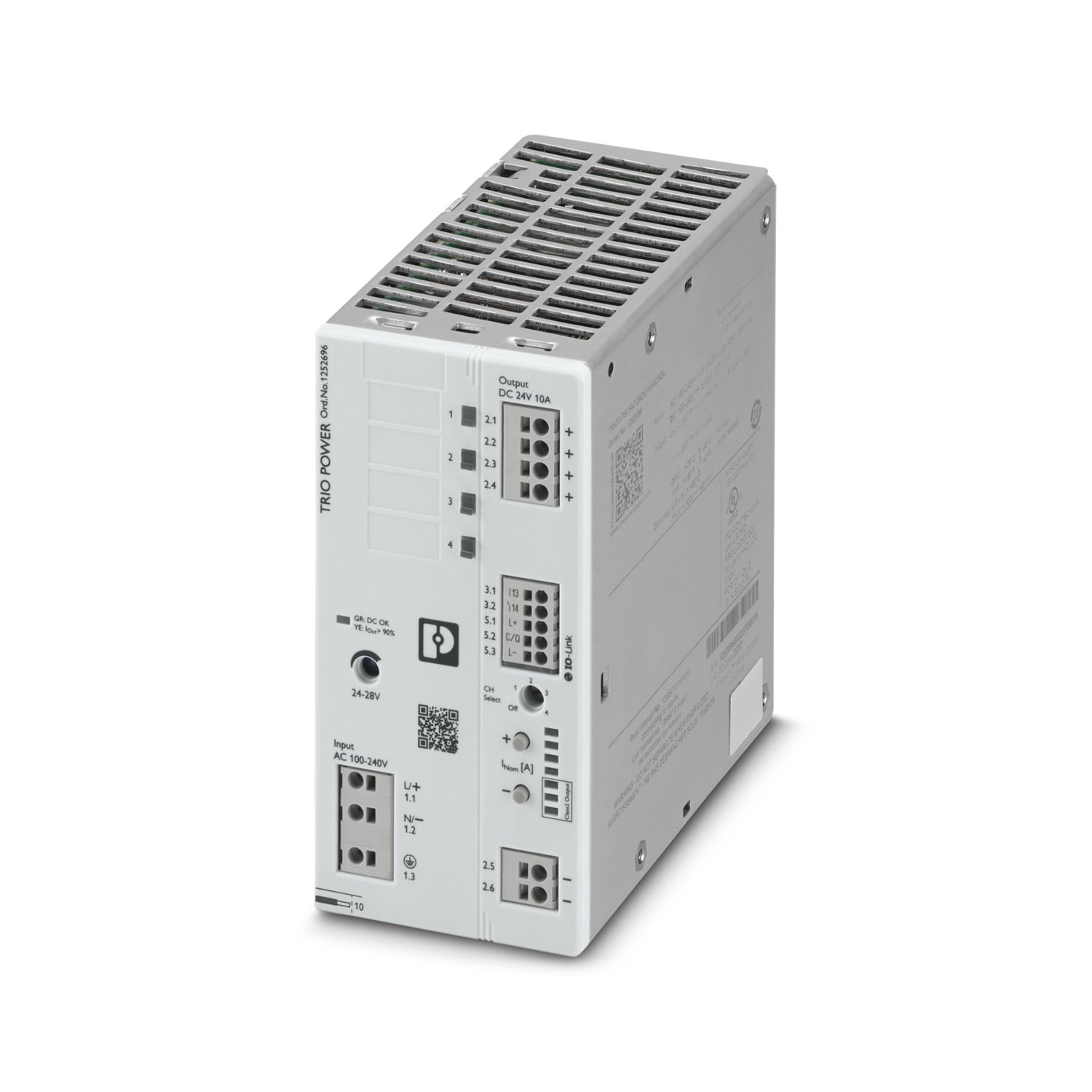
Phoenix Contact TRIO3-PS/1AC/24DC/10/4C/IOL gehört als Netzteil zur Reihe TRIO POWER. Es liefert nominal 24 V DC am Ausgang. Es wird auf einer DIN-Schiene montiert und hat die Schutzart IP20.
Spezifikationen
| Brand | Phoenix Contact |
|---|---|
| Model | TRIO3-PS/1AC/24DC/10/4C/IOL |
| Order Number | 1252696 |
| HS Code | 850440 |
| Interface | IO-Link |
| Voltage | 10 V (Test Level 3) |
| Frequency | 50 Hz |
| Inrush current | < 17 A (25 °C) |
| Nominal output voltage | 24 V DC |
| Power factor | 0.95 (230 V AC) |
| Power loss nominal load max. | < 12 W (230 V AC) |
| Switching voltage | max. 30 V DC (SELV) |
| Typical national grid voltage | 120 V AC |
| Voltage type of supply voltage | AC |
| Cycle time | 40 ms |
| Frequency range | 0 kHz ... 2 kHz |
| Input voltage range | 100 V AC ... 240 V AC -15 % ... +10 % |
| Nominal input voltage range | 100 V AC ... 240 V AC |
| Transmission speed | 38.4 kbps (COM2) |
| Degree of protection | IP20 |
| Depth (Device depth (DIN rail mounting)) | 125 mm (Device depth (DIN rail mounting)) |
| Integrated fuse protection | yes |
| Recommended breaker for input protection | 6 A ... 16 A (Characteristic B, C, D, K or comparable) |
| Reverse polarity protection | yes |
| Vibration (operation) | 10 Hz ... 50 Hz, amplitude ±0.2 mm (IEC 60068-2-6) |
| Vibration (operation) | 50 Hz ... 150 Hz, 2.3g, 90 min. |
| REACH candidate substance (CAS No.) | Lead (CAS: 7439-92-1) |
| Additional text | Class 3 |
| Ambient temperature (operation) | -25 °C ... 70 °C (> 60 °C Derating: 2,5 %/K) |
| Ambient temperature (start-up type tested) | -40 °C |
| Ambient temperature (storage/transport) | -40 °C ... 85 °C |
| Amount of process data | 6 Byte (Input data) |
| AWG (recommended) | 16 (recommended) |
| AWG (recommended) | 20 (recommended) |
| AWG (Terminal block) | 24 ... 12 (Cu) |
| AWG (Terminal block) | 24 ... 16 (Cu) |
| Color | red, yellow, green (multicolor LED) |
| Comments | Criterion B |
| Comments | Criterion A |
| Connection in parallel | no |
| Connection in series | no |
| Connection method | Push-in connection |
| Contact discharge | 6 kV (Test Level 3) |
| Control deviation | < 1 % (change in load, static 10 % ... 90 %) |
| Control deviation | < 3 % (change in load, dynamic 10 % ... 90 %) |
| Control deviation | < 0.1 % (change in input voltage ±10 %) |
| Crest factor | typ. 1.75 (120 V AC) |
| Crest factor | typ. 1,7 (230 V AC) |
| Criterion A | Normal operating behavior within the specified limits. |
| Criterion B | Temporary impairment to operational behavior that is corrected by the device itself. |
| Criterion C | Temporary adverse effects on the operating behavior, which the device corrects automatically or which can be restored by actuating the operating elements. |
| Current carrying capacity | max. 100 mA |
| Current consumption | 2.6 A (100 V AC) |
| Current consumption | 2.2 A (120 V AC) |
| Current consumption | 1.2 A (230 V AC) |
| Current consumption | 1.1 A (240 V AC) |
| Current consumption | 2.7 A (100 V DC) |
| Current consumption | 1.1 A (240 V DC) |
| Degree of pollution | 2 |
| Depth | 132 mm |
| Derating | < 100 V AC (1 %/V) |
| Derating | 2.5 %/K, > 60 °C |
| Derating | < 140 V DC (1 %/V) |
| Derating | 60 °C ... 70 °C |
| Device ID | 040114 hex /262420 dez |
| Device mains fuse | 6.3 A internal (device protection) |
| Discharge current to PE | < 3.5 mA |
| Discharge in air | 8 kV (Test Level 3) |
| Dynamic Boost (I Dyn.Boost ) | max. 15 A (5 s) |
| ECLASS-13.0 | 27040701 |
| ECLASS-15.0 | 27040701 |
| Efficiency | typ. 94.5 % (120 V AC) |
| Efficiency | typ. 95.5 % (230 V AC) |
| Electric strength, max. | 300 V AC 15 s |
| Electromagnetic compatibility | Conformance with EMC Directive 2014/30/EU |
| Environment friendly use period (EFUP) | EFUP-25 An article-related China RoHS declaration table can be found in the download area for the respective article under "Manufacturer declaration". For all articles with EFUP-E, no China RoHS declaration table issued and required. |
| Environmental protection directive | RoHS Directive 2011/65/EU |
| Environmental protection directive | WEEE |
| Environmental protection directive | Reach |
| ETIM 10.0 | EC002540 |
| Exemption | 34, 6(c), 7(a), 7(a)-I, 7(c)-I |
| Feedback voltage resistance | ≤ 35 V DC |
| Flammability rating according to UL 94 | V0 (Housing, terminal blocks) |
| flexible (empfohlen) | 1.5 mm² (recommended) |
| flexible (empfohlen) | 0.5 mm² (recommended) |
| flexible (Klemme) | 0.2 mm² ... 2.5 mm² |
| flexible (Klemme) | 0.2 mm² ... 1.5 mm² |
| flexible with ferrule with plastic sleeve (recommended) | 1.5 mm² (recommended) |
| flexible with ferrule with plastic sleeve (recommended) | 0.5 mm² (recommended) |
| flexible with ferrule with plastic sleeve (Terminal block) | 0.25 mm² ... 2.5 mm² |
| flexible with ferrule with plastic sleeve (Terminal block) | 0.25 mm² ... 0.75 mm² |
| flexible with ferrule without plastic sleeve (recommended) | 1.5 mm² (recommended) |
| flexible with ferrule without plastic sleeve (recommended) | 0.5 mm² (recommended) |
| flexible with ferrule without plastic sleeve (Terminal block) | 0.25 mm² ... 2.5 mm² |
| flexible with ferrule without plastic sleeve (Terminal block) | 0.25 mm² ... 2.5 mm² (Cu) |
| flexible with ferrule without plastic sleeve (Terminal block) | 0.25 mm² ... 1.5 mm² (Cu) |
| flexible with ferrule without plastic sleeve (Terminal block) | 0.25 mm² ... 1.5 mm² |
| Frequency range | 80 MHz ... 1 GHz |
| Frequency range | 1 GHz ... 6 GHz |
| Frequency range | 0.15 MHz ... 80 MHz |
| Frequency range (f N ) | 50 Hz ... 60 Hz ±10 % |
| Fulfills EU RoHS substance requirements | Yes |
| Function | Visual operating state display |
| Function | Operating state forwarding |
| Fuse protection (secondary side) | electronic |
| Height | 135 mm |
| Hood version | Polycarbonate |
| Identification | UL/C-UL Listed UL 61010-1 |
| Identification | UL/C-UL Listed UL 61010-2-201 |
| Identification | UL 1310 / CSA C22.2 No. 223 (NEC Class 2) |
| Identification | UL 2367 (Standard for Safety for Solid State Overcurrent Protectors) |
| Identification | PROCESS CONTROL EQUIPEMENT FOR HAZARDOUS LOCATIONS |
| Identification | (EN) This equipment is suitable for use in Class I, Division 2, Groups A, B, C and D, Hazardous Locations, or non-hazardous locations only. (FR) Cet appareil convient uniquement pour une utilisation en atmosphères explosibles de classe I, division 2, groupes A, B, C et D ou en atmosphères non explosibles. |
| Identification | (EN) If the equipment is used in a manner not specified by the manufacturer, the protection provided by the equipment may be impaired. (FR) Si l'équipement est utilisé d'une manière non spécifiée par le fabricant, la protection fournie par cet équipement peut être altérée. |
| Identification | (EN) This equipement must be installed in a suitable, tool secured/key locked enclosure. (FR) Cet équipement doit être installé dans un boîtier approprié, verrouillé par une clé ou dont l'ouverture nécessite l'utilisation d'un outil. |
| Input | asymmetrical 2 kV (Test Level 3) |
| Input | symmetrical 2 kV (Test Level 4) |
| Input | asymmetrical 4 kV (Test Level 4) |
| Input voltage range | 115 V AC ... 240 V AC ±10 % (UL) |
| Input voltage range | 100 V DC ... 240 V DC ±10 % |
| Input voltage range | 160 V DC ... 240 V DC ±10 % (UL) |
| Input/output/signal | asymmetrical |
| Inrush current integral (I 2 t) | < 0.5 A 2 s |
| Installation distance right/left (active) | 15 mm / 15 mm |
| Installation distance right/left (passive) | 0 mm / 0 mm (≤ 40 °C) |
| Insulation voltage input/output | 3 kV AC (type test) |
| Insulation voltage input/output | 3.1 kV DC (routine test) |
| Interference emission | Interference emission in accordance with EN 61000-6-3 (residential and commercial) and EN 61000-6-4 (industrial) |
| LED off | Supply voltage input AC not present (Off) |
| LED on (flashing red) OVP | U OUT > OVP (Over voltage protection) (on (flashing red)) |
| LED on (green), DC OK | U Out > 21 V DC and I Out < 0.9 x I N (On (green), DC OK) |
| LED on (yellow), IOut > 90 % | U Out > 21 V DC and I Out > 0.9 x I N (On (yellow), I Out > 90% ) |
| Low Voltage Directive | Conformance with Low Voltage Directive 2014/35/EC |
| Mains buffering time | typ. 27 ms (120 V AC) |
| Mains buffering time | typ. 28 ms (230 V AC) |
| Max. capacitive load | 30 mF |
| Max. permissible relative humidity (operation) | ≤ 95 % (at 25 °C, non-condensing) |
| Maximum altitude (Maximum) | ≤ 5000 m |
| Maximum altitude (Output power derating) | > 2000 m (Derating: 10%/1000 m) |
| Maximum no-load power dissipation | < 1.3 W (230 V AC) |
| Minimum no-load power dissipation | < 1.2 W (120 V AC) |
| Minimum nominal load power dissipation | < 14.5 W (120 V AC) |
| Minimum order quantity | 1 pc |
| Mounting position | horizontal DIN rail NS 35, EN 60715 |
| Mounting type | DIN rail mounting |
| MTBF (IEC 61709, SN 29500) | > 1300000 h (25 °C) |
| MTBF (IEC 61709, SN 29500) | > 860000 h (40 °C) |
| MTBF (IEC 61709, SN 29500) | > 400000 h (60 °C) |
| No-load proof | yes |
| No. of channels | 4 |
| Noise immunity | Immunity in accordance with EN 61000-6-1 (residential), EN 61000-6-2 (industrial) |
| Nominal current per channel | 1 A |
| Nominal current per channel | 2 A |
| Nominal current per channel | 3.8 A |
| Nominal current per channel | 4 A |
| Nominal current per channel | 6 A |
| Nominal current per channel | 8 A |
| Nominal current per channel | 10 A |
| Nominal output current (I N ) | 10 A |
| Number of interfaces | 1 |
| Number of periods | 25 periods |
| Number of periods | 12 periods |
| Number of periods | 1 period |
| Number of phases | 1 |
| Output | asymmetrical 2 kV (Test Level 3) |
| Output | symmetrical 1 kV (Test Level 3) |
| Output power (P Dyn. Boost ) | max. 360 W (5 s) |
| Output power (P N ) | 240 W |
| Overvoltage category (EN 61010-1) | III (≤ 2000 m) |
| Overvoltage category (EN 61010-1) | II (≤ 5000 m) |
| Overvoltage category (EN 61010-2-201) | III (≤ 2000 m) |
| Overvoltage category (EN 61010-2-201) | II (≤ 5000 m) |
| Packing unit | 1 pc |
| Position | 1.x |
| Position | 2.x |
| Position | 3.x |
| Position | 5.x |
| Position marking | 1.1 (L/+), 1.2 (N/-), 1.3 () |
| Position marking | 2.1, 2.2, 2.3, 2.4 (+) |
| Position marking | 2.5, 2.6 (-) |
| Position marking | 3.1 (13), 3.2 (14) |
| Position marking | 5.1 (L+), 5.2 (C/Q), 5.3 (L-) |
| Product key | CMPD16 |
| Product type | Power supply |
| Protection against overvoltage at the output (OVP) | ≤ 35 V DC |
| Protection class | I |
| Protective circuit | Transient protection; Varistor |
| Rated current (pre-adjusted) | 1 A |
| Residual ripple | typ. 50 mV PP (with nominal values) |
| rigid (recommended) | 1.5 mm² (recommended) |
| rigid (recommended) | 0.5 mm² (recommended) |
| rigid (Terminal block) | 0.2 mm² ... 4 mm² |
| rigid (Terminal block) | 0.2 mm² ... 1.5 mm² |
| Rise time | ≤ 1 s (U Out = 10 % ... 90 %) |
| Scip | 7cc1364d-c1ae-4ec9-be8a-5f15341697d1 |
| Setting range of the output voltage (U Set ) | 24 V DC ... 28 V DC (> 24 V DC, constant capacity restricted) |
| Shock (operation) | 18 ms, 30g, per spatial direction (IEC 60068-2-27) |
| Short-circuit-proof | yes |
| Side element version | Aluminum |
| Signal | asymmetrical 1 kV (Test Level 2) |
| Special properties | The product is being prepared for compliance with the Cyber Resilience Act (CRA) |
| Specification | V1.1 |
| Standard designation | Electrical safety |
| Standard designation | Safety for equipment for measurement, control, and laboratory use |
| Standard designation | Safety extra-low voltage |
| Standard designation | Protective extra-low voltage |
| Standard designation | Safe isolation |
| Standard designation | Limitation of harmonic line currents |
| Standard designation | Mains variation/undervoltage |
| Standards/regulations | EN 55016 |
| Standards/regulations | EN 61000-6-3 (Class B) |
| Standards/regulations | EN 61000-3-2 |
| Standards/regulations | EN 61000-3-2 (Class A) |
| Standards/regulations | EN 61000-3-3 |
| Standards/regulations | EN 61000-4-2 |
| Standards/regulations | EN 61000-4-3 |
| Standards/regulations | EN 61000-4-4 |
| Standards/regulations | EN 61000-4-5 |
| Standards/regulations | EN 61000-4-6 |
| Standards/regulations | EN 61000-4-11 |
| Standards/specifications | DIN EN 61558-2-16 |
| Standards/specifications | IEC 61010-2-201 (SELV) |
| Standards/specifications | IEC 61010-1 |
| Standards/specifications | IEC 61010-1 (SELV) |
| Standards/specifications | IEC 61010-2-201 (PELV) |
| Standards/specifications | IEC 61558-2-16 |
| Standards/specifications | IEC 61010-2-201 |
| Standards/specifications | EN 61000-3-2 |
| Standards/specifications | SEMI F47 |
| Standards/specifications | EN 61000-4-11 |
| State condition (Contact closed) | U Out > 21 V DC and I Out < 0.9 x I N (Contact closed) |
| State condition (Contact open) | U Out < 21 V DC or I Out > 0.9 x I N (averaging over 60 s) (Contact open) |
| State condition (Contact open_1) | Channel triggered or defective or OVP active |
| Stripping length (starr/flexibel) | 10 mm (Rigid/flexible/ferrule) |
| Supply system configuration | Star network (TN, TT, IT (PE)) |
| Switch contact (floating) | OptoMOS |
| Switch-on delay of the channels | 100 ms |
| Temperature code | T4 (-25 ... +70 °C; > 60 °C, Derating: 2,5 %/K) |
| Test field strength | 10 V/m (Test Level 3) |
| Transmission physics | 3-wire, standard industrial cable |
| Type of signaling | DC OK switch contact - signal state operation (U N = 24 V DC, I Out = I N ) |
| Types of signaling | LED DC OK - signal state operation (U N = 24 V DC, I Out = I N ) |
| Typical national grid voltage | 230 V AC |
| UNSPSC 21.0 | 39121000 |
| Vendor ID | 00B0 hex / 176 dez |
| Voltage | 230 V AC |
| Voltage dip | 70 % |
| Voltage dip | 50 % |
| Voltage dip | 0 % |
| Voltage type of supply voltage | DC |
| Waiting time after switch off of a channel | 5 s |
| Weight per piece (excluding packing) | 861 g |
| Weight per piece (including packing) | 960 g |
| Width | 68 mm |
| With protective coating | no |