Kategorien durchsuchen
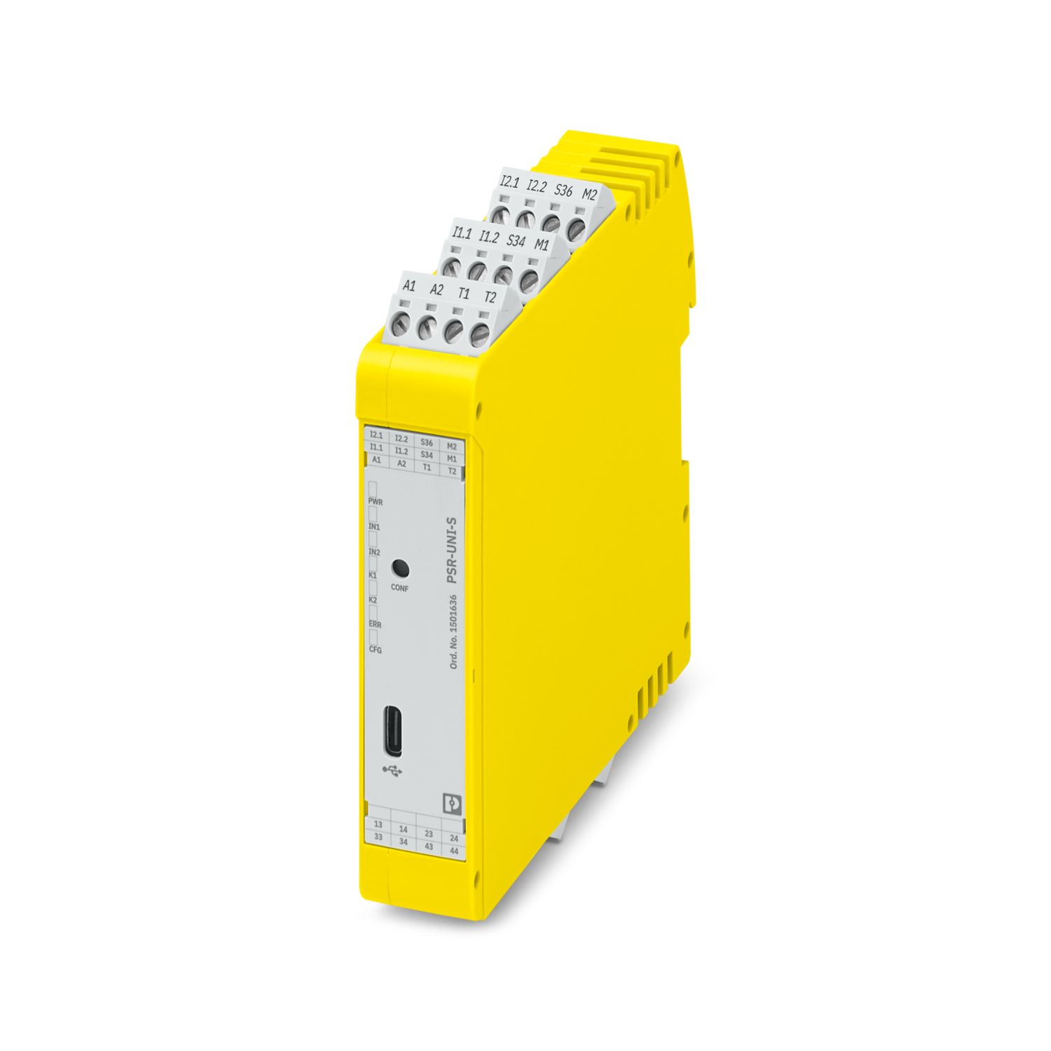
Phoenix Contact PSR-UNI-S-2X2NO-2DO-24DC-SC Sicherheitsrelais
Beschreibung
Phoenix Contact PSR-UNI-S-2X2NO-2DO-24DC-SC gehört als Sicherheitsrelais zur Reihe PSRuni. Es ist für Not-Halt-Schaltungen spezifiziert. Es wird auf einer DIN-Schiene montiert und hat die Schutzart IP20.
Spezifikationen
| Brand | Phoenix Contact |
|---|---|
| Model | PSR-UNI-S-2X2NO-2DO-24DC-SC |
| Order Number | 1501636 |
| Voltage | typ. (U S - 2,5 V) |
| Switching frequency | max. 0.1 Hz |
| Current | max. 100 mA (observe derating) |
| Power consumption | max. 100 mW (typical) |
| Input voltage | 5 V DC |
| Input current | < 20 mA |
| Inrush current | typ. 50 A (Δt = 25 µs at U s ) |
| Limiting continuous current | 6 A |
| Maximum inrush current | 500 mA (Δt = 100 ms at U s ) |
| Power consumption at U S | typ. 1.56 W |
| Rated insulation voltage | 250 V |
| Sq. Total current | 144 A 2 (K1 = 72 A², K2 = 72 A², observe derating) |
| Switching voltage | min. 10 V AC/DC |
| Delay time range | 0.1 s ... 300 s ± 3% (optionally parameterizable switch-on or switch-off delay, see section “Calculation of typical delay times”) |
| Limit frequency | min. 0 Hz |
| Degree of protection | IP20 |
| Reverse polarity protection | yes (Serial) |
| Short-circuit protection | Yes |
| Vibration (operation) | 10 Hz ... 150 Hz, 2g |
| REACH candidate substance (CAS No.) | Lead (CAS: 7439-92-1) |
| Ambient temperature (operation) | -25 °C ... 60 °C (observe derating) |
| Ambient temperature (storage/transport) | -40 °C ... 85 °C |
| Application | Emergency stop |
| Application | Safety door |
| Application | Light grid |
| Application | Magnetic switch |
| Application | Two-hand control |
| Application | Safety shut-off mats |
| Cable length | See inputs |
| Color | yellow (RAL 1018) |
| Concurrence | ∞ (2-channel wiring), 5 s (non-equivalent wiring), 0.5 s (two-hand control, synchronous activation monitoring) |
| Conductor cross-section AWG | 24 ... 12 |
| Conductor cross-section flexible | 0.2 mm² ... 2.5 mm² |
| Conductor cross-section rigid | 0.2 mm² ... 2.5 mm² |
| Connection method | Screw connection |
| Connection method | USB type C |
| Contact material | AgCuNi, +0.2 ... 0.4 µm Au |
| Contact switching type | 4 enabling current paths |
| Control | 1 and 2 channel |
| Current | max. 100 mA |
| Current consumption | 3.5 mA (typ. with U S ) |
| Current consumption | < 3.5 mA (typ. with U S ) |
| Degree of pollution | 2 |
| Depth | 111.7 mm |
| Description of the input | safety-related |
| Description of the input | IEC 61131-2 type 3 |
| Description of the input | non-safety-related |
| Designation | A1/A2 |
| Discharging circuit | no |
| ECLASS-13.0 | 27371819 |
| ECLASS-15.0 | 27371819 |
| Environment friendly use period (EFUP) | EFUP-50 An article-related China RoHS declaration table can be found in the download area for the respective article under "Manufacturer declaration". For all articles with EFUP-E, no China RoHS declaration table issued and required. |
| Error indication | 1 x LED (red) |
| ETIM 10.0 | EC001449 |
| Exemption | 7(a), 7(c)-I |
| Filter time | 1 ms (logic) |
| Filter time | max. 3 ms (Test pulse width of low test pulses) |
| Filter time | min. 50 ms (Test pulse rate for low test pulse) |
| Filter time | < 1 ms (High test pulses at >100 ms test pulse rate possible) |
| Fulfills EU RoHS substance requirements | Yes |
| Height | 112.7 mm |
| Housing material | PA |
| Input current range "0" signal | 0 mA ... 1.5 mA |
| Input voltage range "0" signal | 0 V DC ... 5 V DC |
| Input voltage range "1" signal | 11 V DC ... 30 V DC |
| Inrush current | < 45 mA (typ. with U S, Δt |
| Inrush current | min. 3 mA |
| Inrush current | max. 6 A |
| Inrush current | < 20 mA |
| Limit frequency | max. 0.1 Hz |
| Max. capacitive load | 15 nF |
| Max. permissible humidity (storage/transport) | 75 % (on average, 85% infrequently, non-condensing) |
| Max. permissible overall conductor resistance | 150 Ω |
| Max. permissible relative humidity (operation) | 75 % (on average, 85% infrequently, non-condensing) |
| Maximum altitude | ≤ 2000 m (Above sea level) |
| Maximum cable length | 3 m |
| Maximum power dissipation for nominal condition | 9.15 W (at U S = 30 V, I L ² = 144 A²) |
| Mechanical service life | 10x 10 6 cycles |
| Min. degree of protection of inst. location | IP54 |
| Minimum order quantity | 1 pc |
| Mounting position | vertical or horizontal |
| Mounting type | DIN rail mounting |
| Nominal operating mode | 100% operating factor |
| Number of connections | 1 |
| Number of inputs | 4 |
| Number of inputs | 2 |
| Number of outputs | 4 |
| Number of outputs | 2 |
| Ohmic load | min. 192 Ω (max. 100 mA) |
| Operating voltage display | 1 x LED (green, yellow, red) |
| Output description | 2 N/O contacts in series, safety-related, floating |
| Output description | non-safety-related |
| Output fuse | 6 A gL/gG |
| Output fuse | 4 A gL/gG (for low-demand applications) |
| Overvoltage category | II, III (See the section “Insulation coordination”) |
| Packing unit | 1 pc |
| Performance level (PL) | e |
| Pluggable | yes |
| Product key | DNA191 |
| Product type | Safety relays |
| Protective circuit | Serial protection against polarity reversal |
| Protective circuit | Suppressor diode |
| Protective circuit | Varistor |
| Protective circuit | Reverse polarity protection |
| Rated control circuit supply voltage U S | 24 V DC -20 % / +25 % |
| Rated control supply current I S | typ. 65 mA (When sensor circuit and start circuit are controlled internally) |
| Rated control supply current I S | typ. 45 mA (When sensor circuit and start circuit are controlled externally) |
| Rated surge voltage/insulation | See data sheet, section “Insulation coordination”. |
| Recovery time | 500 ms (following demand of the safety function) |
| Recovery time | > 100 ms (Availability time after activating the sensor circuit during manual start) |
| Recovery time | > 500 ms (Availability time after activating the sensor circuits during manual start in safety shut-off mat operation) |
| Relay type | Electromechanical relay with force-guided contacts in accordance with IEC/EN 61810-3 |
| Restart time | < 1 s (Boot time) |
| Safety Integrity Level (SIL) | 3 |
| Screw thread | M3 |
| Shock | 15g |
| Start pulse length | min. 500 ms (manual start) |
| Status display | 5 x LED (green, yellow, red) |
| Stop category (EN 60204-1) | 0 |
| Stop category (EN 60204-1) | 1 (with parameterized switch-off delay) |
| Stripping length | 7 mm |
| Switching capacity | 5 A (DC 13) |
| Switching capacity | 3 A (AC 15) |
| Switching power | min. 60 mW |
| Switching voltage | max. 250 V AC/DC |
| Tightening torque | 0.5 Nm ... 0.6 Nm |
| Typ. starting time with U s | 1 s (when controlled via A1; applicative control via A1/A2 is not permitted.) |
| Typ. starting time with U s | Applies to parameterization: switch-off delay or no delay. For switch-on delay, see section “Calculation of typical delay times”. |
| Typical release time | < 25 ms (on demand via the sensor circuit) |
| Typical release time | < 85 ms (Safety shut-off mat operation) |
| Typical release time | < 25 ms (when requested via A1; applicative deactivation via A1/A2 is not permitted.) |
| Typical release time | Applies to parameterization: switch-on delay or no delay. For switch-off delay, see section “Calculation of typical delay times”. |
| Typical response time | < 100 ms (Automatic/manual start) |
| Typical response time | < 500 ms (Safety shut-off mat operation) |
| Typical response time | Applies to parameterization: switch-off delay or no delay. For switch-on delay, see section “Calculation of typical delay times”. |
| Weight per piece (excluding packing) | 213.2 g |
| Weight per piece (including packing) | 235.2 g |
| Width | 22.5 mm |