Kategorien durchsuchen
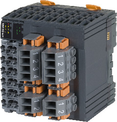
B&R X20CM0985 Analogeingabemodul
Beschreibung
Das Analogeingabemodul B&R X20CM0985 bietet Stromeingangsimpedanz auf 3 Kanälen und Spannungsmessung auf 8 Kanälen.
Spezifikationen
| Brand | B&R |
|---|---|
| MPN | X20CM0985 |
| Nominal output current | 1 A at 30 VDC / 1 A at 240 VAC |
| Cutoff frequency | 10 kHz |
| Nominal output current | 0.1 A |
| Nominal voltage | 30 VDC / 240 VAC |
| Nominal voltage | 24 VDC |
| Switching voltage | Max. 60 VDC / 250 VAC |
| Switching voltage | 24 VDC -15% / +20% |
| Total nominal current | 0.5 A |
| Cutoff frequency | 10 kHz |
| Input impedance in signal range | Approx. 3 MΩ |
| Rated frequency | DC / 45 to 63 Hz |
| Input protection | Overvoltage protection |
| Output protection | Thermal shutdown in the event of overcurrent or short circuit |
| AC | RC combination or VDR |
| Actuator power supply | External |
| Analog inputs | Yes, using LED status indicator (measurement range of analog inputs) |
| ATEX | Zone 2, II 3G Ex nA nC IIA T5 Gc IP20, Ta (see X20 user's manual) FTZÚ 09 ATEX 0083X |
| B&R ID code | 0x2433 |
| Bus | 1.4 W |
| CE | Yes |
| Channel - Bus | 4000 VAC / 1 min |
| Channel - Channel | 1000 VAC / 1 min |
| Channels | 3 |
| Channels | 8 |
| Connection type | 1-wire connections |
| Contact resistance | Max. 100 mΩ |
| Conversion method | SAR |
| Conversion method | SAR |
| Conversion time | 20 ms |
| Conversion time | 16.67 ms |
| Conversion time | 20 ms |
| Conversion time | 16.67 ms |
| CRA (Cyber Resilience Act) | In preparation |
| Crosstalk between channels | -70 dB |
| Crosstalk between channels | -70 dB |
| DC | Inverse diode, RC combination or VDR |
| Diagnostic status | Output monitoring with 10 ms delay |
| Digital converter resolution | ±15-bit |
| Digital converter resolution | ±15-bit |
| Digital outputs | Yes, using LED status indicator and software |
| Electrical | Min. 60 x 10 3 ops. (NC) at 1 A Min. 30 x 10 3 ops. (NO) at 1 A |
| Electrical isolation | Bus isolated from I/O power supply and digital inputs and outputs Digital inputs and outputs isolated from each other |
| External | None |
| Gain | 0.2% |
| Gain | 0.09% |
| HazLoc | cCSAus 244665 Process control equipment for hazardous locations Class I, Division 2, Groups ABCD, T5 |
| Horizontal | Yes |
| Horizontal mounting orientation | 0 to 60°C |
| Input | 1 A / 5 A AC |
| Input | 120 VAC / 480 VAC |
| Input impedance | Max. 30 mΩ |
| Input impedance | Max. 10 mΩ |
| Input type | Isolated current transformer according to the compensation principle with a magnetic sensor, for connecting an external transformer |
| Input type | Single-ended |
| Installation elevation above sea level | Reduction of ambient temperature by 0.5°C per 100 m |
| Installation elevation above sea level | No limitation |
| Installation elevation above sea level | IP20 |
| Insulation voltage between channel and bus | 500 V eff |
| Insulation voltage between channel and bus | 500 V eff |
| Internal | None |
| Internal I/O | 4 W |
| KC | Yes |
| Leakage current when the output is switched off | 5 μA |
| Max. | 30 W / 240 VAC |
| Maximum gain drift | 0.07% per °C |
| Maximum gain drift | 0.02% per °C |
| Maximum offset drift | 0.003% per °C |
| Maximum offset drift | 0.003% per °C |
| Mechanical | Min. 10 x 10 6 ops. |
| Min. | 10 mA / 5 VDC |
| Module run/error | Yes, using LED status indicator and software |
| Monitored overcurrent | 4 x I Nom |
| Nonlinearity | ≤0.5% at 45 to 65 Hz |
| Nonlinearity | ≤0.5% at 45 to 65 Hz |
| Offset | 0.05% |
| Offset | 0.03% |
| Operation | 5 to 95%, non-condensing |
| Output circuit | Source |
| Output format | 1 LSB = 0x0001 = 189.903 μA |
| Output format | 1 LSB = 0x0001 = 949.513 μA |
| Output format | 1 LSB = 0x0001 = 5.707 mV |
| Output format | 1 LSB = 0x0001 = 22.787 mV |
| Output format | INT |
| Output format | INT |
| Overshoot | 0x7FFF |
| Overshoot | 0x7FFF |
| Overvoltage category | ll |
| Permissible input signal | Max. 1.5 A / 7.7 A |
| Permissible input signal | Max. 132 VAC / 528 VAC |
| Pitch | 87.5 +0.2 mm |
| Protection against electric shock | Protective impedance per EN 61131-2 |
| Quantity | 1 |
| Quantity | 5 |
| Resistive load | Max. 100 Hz |
| Slope | 60 dB |
| Slope | 60 dB |
| Status indicators | Channel status, operating state, module status |
| Storage | -40 to 85°C |
| Storage | 5 to 95%, non-condensing |
| Switch-on in the event of overload shutdown or short-circuit shutdown | Approx. 10 ms, depends on the module temperature |
| Switching delay | ≤10 ms |
| Switching delay | ≤10 ms |
| Test voltage between channel and bus (type test) | 3700 V eff |
| Thermal overcurrent | 15 x I Nom for 0.2 s |
| Transport | -40 to 85°C |
| Transport | 5 to 95%, non-condensing |
| UKCA | Yes |
| UL | cULus E115267 Industrial control equipment |
| Undershoot | 0x8001 |
| Undershoot | 0x8001 |
| Variant | Relay / Changeover contact |
| Variant | Current-sourcing FET |
| Vertical | Yes |
| Vertical mounting orientation | 0 to 50°C |